


2026 How to Choose the Right Electrical Switchgear Box?

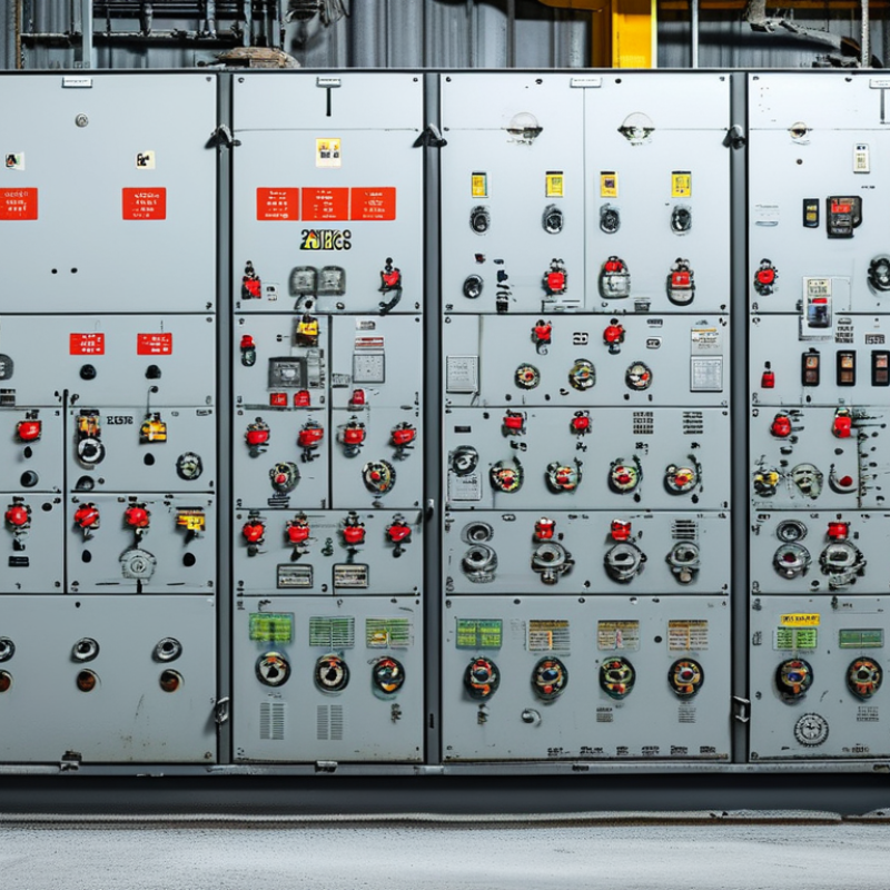
Choosing the right Electrical Switchgear Box in 2026 requires more than comparing prices or enclosure sizes. It demands practical judgment. The box must match the system voltage, rated current, fault level, installation environment, and future expansion plans. A cabinet beside a clean indoor panel room faces different risks from one installed near salt air, dust, heat, or machinery vibration.

Dr. J. C. Das, a respected power-system author, offers a useful principle: “Select switchgear for the complete system duty, not merely the normal load.” This idea remains highly relevant. Engineers should examine short-circuit withstand ratings, insulation coordination, busbar spacing, cable-entry design, grounding, and protection-device compatibility. An IP rating alone does not guarantee dependable performance. It only describes defined protection conditions.

Look closely at the details.

For outdoor applications, corrosion-resistant materials and sealed cable glands may matter more than appearance. For industrial sites, arc-flash mitigation, interlocking, thermal management, and safe maintenance access deserve serious attention. Factory testing, routine inspection records, and conformity with applicable IEC or regional standards also strengthen purchasing confidence. Supplier experience matters, especially when the project needs custom compartments or complicated feeder arrangements.

The cheapest enclosure can become the costliest decision.

Still, no selection guide can remove every uncertainty. Load growth may be underestimated. Site conditions may change. Even a well-designed Electrical Switchgear Box can fail when installation workmanship is careless. A reliable choice therefore combines calculations, field verification, documented testing, and honest communication with the manufacturer. This 2026 guide examines those practical decisions, including the common assumptions that deserve a second look.
2026 How to Choose the Right Electrical Switchgear Box?

Define Application Voltage, Current and IEC 61439 Assembly Requirements

2026 How to Choose the Right Electrical Switchgear Box?

Define Application Voltage, Current and IEC 61439 Assembly Requirements

Start with the application, not the enclosure size. Record the system voltage, frequency, earthing arrangement, and installation location. Is the switchgear indoors, outdoors, dusty, humid, or exposed to impact? A workshop panel may need a different IP rating from a clean control room panel. Simple details matter.

Calculate the expected load current from real operating conditions. Include motors, heaters, lighting, transformers, and future expansion. Motor starting current can exceed running current several times. Diversity factors also require engineering judgment. A common mistake is selecting the box from the total nameplate current alone. It may run hot. Define the assembly rated current, operational voltage, and short-circuit withstand requirements before choosing components.

IEC 61439 focuses on the complete low-voltage assembly, not just its cabinet. Check rated insulation voltage, temperature-rise limits, creepage distances, clearances, and internal separation. Verify the required Icw and Ipk values against the available fault level.

The design should also address busbar support, protective devices, cable entry, ventilation, and mechanical strength. Routine verification should cover wiring, protective circuits, insulation, and functional performance.

Keep calculation sheets and test records with the project file. A neat box can still be technically unsuitable.

In practice, designers sometimes underestimate spare space, especially after adding larger cables or auxiliary devices. Allow room for maintenance, safe termination, and measured heat dissipation.

Match Short-Circuit Ratings from 10 kA to 100 kA under IEC 60947-2

2026 How to Choose the Right Electrical Switchgear Box?

Choosing a switchgear box starts with the prospective short-circuit current at its installation point. Under IEC 60947-2, ratings from 10 kA to 100 kA are not interchangeable labels. Check the system voltage, frequency, earthing arrangement, and available fault current. A breaker rated 25 kA at one voltage may have a lower rating at another.

Compare the ultimate short-circuit breaking capacity, Icu, with the calculated fault level. Also review the service breaking capacity, Ics, because equipment may need to operate safely after clearing a fault. For example, a panel facing an 18 kA fault level may require a 25 kA device, subject to engineering margins and local conditions. Do not simply select 100 kA because it appears safer. It may increase cost, size, and coordination problems.

Inspect the complete assembly, not only the breaker. Busbars, terminals, cables, enclosure strength, and heat dissipation must withstand the expected fault energy. Verify manufacturer test certificates and coordination data against IEC 60947-2. Backup protection or cascading is acceptable only when documented for the exact combination. In real projects, drawings sometimes show a rating without recording the calculation. That is a weakness worth correcting. Measure or calculate the fault current, record the assumptions, and recheck the selection during commissioning.

2026 How to Choose the Right Electrical Switchgear Box?

Match Short-Circuit Ratings from 10 kA to 100 kA under IEC 60947-2

The chart shows reference ultimate short-circuit breaking capacity levels (Icu) commonly specified for low-voltage circuit-breakers. Select an Icu rating at or above the calculated prospective short-circuit current at the installation point. Final verification must also consider the system voltage, frequency, installation conditions, coordination requirements, and the declared service short-circuit rating (Ics).

The displayed values are reference rating levels, not a universal IEC 60947-2 selection sequence. Always confirm the manufacturer’s certified rating at the actual operating voltage.

Choose IP54–IP66 Enclosures Using IEC 60529 Ingress Protection Ratings

Choosing an electrical switchgear box starts with its environment, not its appearance. IEC 60529 defines the IP code used to describe enclosure protection. In IP54, the first 5 means protection against harmful dust deposits. The second 4 indicates protection from water splashes in all directions. IP55 handles water jets, while IP65 adds complete dust-tight protection. IP66 remains dust-tight and withstands more powerful water jets.

An indoor plant room may suit IP54 when dust and moisture remain limited. Outdoor cabinets often need IP65 or IP66, especially near washdown areas.

However, IP66 is not automatically the wiser choice. That assumption needs challenging. Higher protection can increase cost, sealing pressure, and maintenance demands. Select the rating after reviewing rain exposure, cleaning methods, cable entry positions, and condensation risks.

Installation details matter as much as the enclosure rating. A poorly fitted cable gland can reduce the entire assembly’s protection. Check door gaskets for compression, damage, and correct alignment. Keep unused entries sealed with compatible components. Review the manufacturer’s IEC 60529 test evidence, not only a printed IP label.

The standard does not rate corrosion, ultraviolet exposure, impact, temperature, or internal heat. A coastal site may need extra material protection. A hot enclosure may require thermal assessment.

I have seen IP ratings treated as permanent guarantees, but field conditions change them quickly. Inspect the box after installation. Recheck it after modifications.

Check Thermal Performance at the IEC 61439 Reference Ambient of 40°C

Choosing the right electrical switchgear box begins with its thermal performance. IEC 61439 uses 40°C as the reference ambient temperature for assembly verification. This value is not a comfortable room temperature. It can occur inside a warm plant, under direct sunlight, or near process equipment.

Check the declared rated current and verified temperature-rise data at 40°C. Then examine heat-producing parts, including circuit breakers, busbars, terminals, and control transformers. Heat leaves slowly. A compact enclosure may look efficient, yet crowded wiring can restrict airflow around connection points. Review the enclosure’s internal layout, ventilation method, installation position, and exposure to dust. Small details matter.

Ask how the design handles realistic loading, not only the nameplate rating. Continuous current, simultaneous operation, and ambient temperature can combine in difficult ways. Measure temperatures during commissioning when possible, especially near cable lugs and upper busbar sections. Infrared readings are useful, but loose connections can remain hidden without proper inspection. A calculation can still mislead if it uses optimistic diversity assumptions. I have seen apparently acceptable designs run hotter after adding a few auxiliary devices. That experience supports a cautious margin, although excessive derating can increase size and cost without improving safety. Check the verification records, installation instructions, and maintenance access before approving the switchgear box.

2026 How to Choose the Right Electrical Switchgear Box? – Check Thermal Performance at the IEC 61439 Reference Ambient of 40°C

Electrical Switchgear Box Selection and Thermal Verification Checklist
Design Dimension IEC 61439 Reference or Engineering Basis What to Check at a 40°C Ambient Realistic Design Data or Calculation Input Selection Decision
Ambient temperature IEC 61439 normal service conditions allow an ambient temperature up to 40°C, with a 24-hour average not exceeding 35°C. Confirm that the installation location does not exceed 40°C under normal operating conditions. Higher temperatures require a specific design assessment. Maximum ambient: 40°C
24-hour average: ≤35°C
Mandatory input
Rated current of the assembly The rated current and diversity of outgoing circuits determine conductor, busbar and device losses. Use the actual simultaneous load current rather than the sum of all circuit ratings. Check the continuous current of the incomer, busbars and feeders. Incomer rating: 400 A
Calculated continuous load: 320 A
Diversity factor: 0.80
Verify by design
Total internal power loss Thermal performance depends on the heat generated by circuit-breakers, contactors, terminals, busbars, cables and auxiliary equipment. Add the heat losses of all continuously energized devices and conductors. Use manufacturer-certified loss data for each component where available. Device losses: 210 W
Busbar and cable losses: 90 W
Auxiliary losses: 25 W
Total design loss: 325 W
Calculate before selection
Enclosure volume The available heat-dissipation area and internal air volume affect the temperature rise. A larger enclosure generally provides better natural convection. Compare the internal volume and usable mounting area with the calculated heat loss. Do not judge thermal capability from external dimensions alone. Internal dimensions: 1,800 × 800 × 300 mm
Approximate internal volume: 0.432 m³
Check the thermal model
Cooling method Natural ventilation, forced ventilation and air-conditioning produce different thermal results and environmental protection levels. Select a cooling method that can remove the calculated heat at 40°C. Filtered fans and air-conditioning require maintenance and auxiliary power. Natural convection: suitable for low-to-moderate losses
Filtered fan: used when natural cooling is insufficient
Air-conditioner: used for high losses or tightly sealed enclosures
Match cooling to heat load
Temperature-rise verification IEC 61439 requires verification of temperature-rise performance by an applicable verification method, such as testing, comparison with a tested design or calculation. Confirm that the calculated or tested temperature rise remains within the limits applicable to the installed components, conductors, terminals and accessible surfaces. Ambient reference: 40°C
Example calculated internal air rise: 28 K
Estimated internal air temperature: 68°C
Document verification
Component temperature rating Individual devices and accessories have their own operating-temperature limits and derating requirements. Check the operating temperature and current derating curve for every major device. The lowest applicable component limit governs the design. Ambient plus internal rise: 68°C
Device-specific rating and derating: must be confirmed from technical documentation
Use component data
Busbar and conductor sizing Current-carrying capacity is affected by conductor material, cross-section, arrangement, spacing, enclosure conditions and operating temperature. Check continuous current, short-circuit withstand, joint heating and proximity effects. Avoid selecting busbars only from the nominal current value. Copper busbar system: 400 A design rating
Continuous operating current: 320 A
Joint and connection temperatures: included in verification
Verify thermal and fault ratings
Ingress protection versus cooling A higher IP rating can restrict airflow and increase internal temperature. The required IP rating depends on the installation environment. Balance dust and water protection with heat dissipation. Ventilation openings must not compromise the specified IP rating. Indoor clean electrical room: IP31–IP42 may be suitable
Dust or water exposure: higher IP rating may be required
Final rating: project and site dependent
Select IP and cooling together
Installation arrangement Wall-mounted, floor-standing, adjacent or enclosed assemblies have different heat-transfer conditions. Allow the required clearance around the enclosure. Do not block ventilation paths or install heat-producing sections directly below sensitive devices without assessment. Side clearance: according to the tested or calculated design
Top ventilation: kept unobstructed where required
Adjacent heat sources: included in the assessment
Confirm site layout
Short-circuit withstand Thermal design does not replace verification of short-circuit withstand for the assembly and its internal conductors. Check short-time withstand current, peak withstand current and protective-device coordination for the prospective fault level. Prospective short-circuit current: 25 kA
Required withstand rating: not less than the calculated fault level
Separate mandatory check
Thermal margin A design margin helps accommodate load variation, blocked ventilation, connection resistance and future circuit additions. Avoid operating continuously at the calculated thermal limit. Recalculate if the load, enclosure layout, IP rating or cooling method changes. Recommended engineering practice: reserve capacity for
future load growth and installation tolerances
Keep practical margin
Required documentation The final assembly design should have traceable evidence for ratings, construction, verification and operating conditions. Retain temperature-rise calculations or test evidence, component loss data, current ratings, IP evidence, fault ratings and installation instructions. Design file includes: thermal calculation, layout, ratings, test or comparison evidence, maintenance requirements Complete before approval
Engineering note: A 40°C ambient is the upper normal service-condition value commonly used for IEC 61439 assemblies; it is not a universal temperature-rise limit for every component. Final acceptance must be based on the complete assembly design, the applicable IEC 61439 verification method, component technical data, installation conditions and the required short-circuit and ingress-protection ratings.

Compare Busbar Materials and Form 2–4 Internal Separation Options

During panel selection, I check the busbar material before comparing enclosure layouts. Copper offers high conductivity and stable joints, but it adds weight and cost. Aluminum is lighter and often economical, yet its oxide layer demands careful joint preparation. Temperature rise, fault current, moisture, and available space must guide the decision. Do not choose by conductivity alone. Site measurements matter.

Form 2 separates busbars from functional units. Form 3 also separates individual functional units from each other. Form 4 provides stronger separation, including terminals for external conductors. This can improve maintenance safety, but it reduces working space and may increase heat concentration. Under IEC 61439 verification, the assembly still needs suitable temperature-rise, short-circuit, and dielectric performance. An experienced engineer should inspect cable access, barriers, and torque records, not only the form number. Form 4 is not automatically better. Sometimes, it is simply oversized.

Tips: Match the separation level to maintenance frequency, operator exposure, and fault consequences. Use copper where compact conductors and high current density are critical. Consider aluminum when weight and budget matter, then specify compatible lugs and joint compounds. Leave ventilation paths clear. Ask for test evidence, drawings, and material certificates. I have seen neat layouts fail because one cable bend blocked a barrier. That detail is easy to miss. Review it twice.

Powder Coat Booths

For those larger-sized parts, or smaller quantity runs, we have 2 independent powder coat booths and ovens. The quality, durability and affordability of today’s powder coating finishes make this the process of choice for world-class companies.

Powder coating advantages over other forms of coating are many. Materials used in the Powder coating process can be metals and non-metals that come in a multitude of thicknesses, textures, colors, etc. Another of Powder coating’s biggest advantages over conventional coatings is its ability to create finishes in many different textures. Powder Coating Booths allow us the ability to apply these advantages to large products.

Wet Paint Line

Tri-State Fabricators runs a full-service conveyor line for painting. Wet painting can provide protection or decoration to many different part styles. From start to finish, every project is easier to undergo random and point-based inspection by our skilled painting team.

Advantages to our Wet Paint Line are these lines start with product prep and ends with a thorough inspection of a high quality finished product. Our ability to complete large and small projects with a superior finish and doing so in a timely and economical fashion. This passes along the savings in production to our customers. When powder coating ins not an option, our Wet Paint Line gets the job done right the first time.

Wet Paint Booths

When the parts get big and heavy we roll-out our custom paint racks and oversize booth. By utilizing our partnerships with all the major paint brands, we can match virtually any color with wet paint.

The advantages of having access to a Wet Paint Booth are many. Large projects of many different shapes can be loaded into the booth. The Wet Paint Booth offers an environment that is much more controlled than a typical parts painting operation.

Not only are they used because of their controlled environment, but they’re are also advantageous when it comes to applying paint to parts that are needed in industries that require specialty coatings such as medical, aerospace, etc.

Military CARC

Our military forces have some very high standards when it comes to the finish of their vehicles and equipment. From the first pre-treatment step to final coat, it takes a great deal of knowledge and experience to protect the men and women of our armed forces. They deserve only the best, and Tri-State Fabricators provides it.

All of our processes are closely monitored by our staff and management teams. Both of which are highly trained in the processes of metal fabrication and finishing. Tri-State Fabricators’ goal is to always fully satisfy each and every customer, including the military. We will always put a 110% into what we do.

Glass-Bead Blasting

Abrasive media blasting is an excellent way to remove old paint, rust, and increase the paint/powder adhesion. Glass beads produce a much smoother and brighter finish than angular abrasives; leaving the part clean yet without any dimensional change. Chemically inert and environmentally friendly, we can recycle our beads approximately 30 times; making them a more preferred method of metal cleaning or surface finishing.

Advantages to Glass Bead Blasting are many. Glass bead blast media is used when a project is needing rough surfaces need to become smooth for applications of coatings such as paint. It is typically used to clean paint and rust from a product surface without deforming the surface it is being used on. Overall, compared to many other blasting media, Glass Bead Blasting is a very economical choice and those savings are always passed on to our customers.

Part Washing

Tri-State Fabricators utilize a zinc phosphate wash to clean and etch the material to ensure the best paint adhesion possible. The unique design of our 3-stage wash system does the work like a 5-stage. From Cleaning and rinsing to conversion coating and post-treatment, Our Part Washing process is a complete service and works throughout the fabrication service and the finishing service.

Along with the previously mentioned benefits, Curing is a vital chemical reaction that leaves the product finish hard and relatively safe from mild abrasion and aggressive corrosion. This process can be done in more than one way; ambient air-dry or in curing ovens at temps that exceed 240°.

Burn-Off Oven

From fixing paint mistakes (someone else’s of course) to simply cleaning our paint line hooks, our burn-off oven is put to good use. After a quick burn-off, a little clean up, and a fresh coat of paint, your parts will look better than new.

Why does our Burn-Off Oven work so well? Because super heating the air around parts turns the materials into ashes. From paint and powder coatings to rubber and machining oils, high temps do the job without degrading the integrity of the part.

Masking

Masking is a vital part of producing high quality products. We have die-cut masking patterns to protect machined surfaces as well as a wide range of plugs and caps to protect threaded holes and bolts. We provide permanent and temporary masking.

Masking allows the selected sections of a product to be protected from a fabrication or finishing service. This can be with both chemicals when etching and tapes, paints when only finishing just a section of the product. Masking is great in aiding the customization process of a project.

Screen Printing

Screen printing is a photographic process that transfers artwork onto a porous nylon screen which allows colored ink to flow through the screen and be deposited on an aluminum or plastic component. We can generally have just about any design created onto a screen for your parts.

Some of the advantages of Screen Printing are, brand recognition for your business displaying on your products, assembly instructions, product warnings/hazards, etc. Tri-State Fabricators produces Screen Printing of the highest quality so you know it’s durable.

Metal Finishing

Metal Finishing is the art of treating the exterior portion of product, often metal but can also be made of other materials, so that the surface is clean and free of any debris. Then the process of applying coats or either paint of powder coat takes place. This coating process improves the quality of the product in both appearance and resistance to wear and corrosion.

Tri-State Fabricators, Inc., understands that a project typically isn’t complete until a high-quality finish has been added to your product. This is why our painting and powder coating teams continuously inspect the products throughout the Metal Finishing process.