


Global buyers entering the 2026 thermal management market need more than a simple list of materials. A Heatsink Thermal Pad must match the device, heatsink surface, pressure, and operating temperature. Small mismatches can create costly hot spots.
Silicone-based gap filler pads remain practical for uneven surfaces and repeated assembly. Ceramic-filled pads can provide electrical insulation with dependable thermal transfer. Graphite pads offer strong in-plane heat spreading, but they may require careful electrical isolation. Phase-change materials can reduce interface resistance after heating, although installation and service conditions need close review. Some newer pads combine compressibility, high conductivity, and low pump-out performance. They sound ideal. They rarely fit every design.
For global purchasing teams, supplier evidence matters. Request thermal conductivity data, thickness tolerance, compression curves, dielectric strength, flammability information, and aging results. Confirm whether testing follows recognized methods, because laboratory values are not always directly comparable. Ask for samples from the same production line, then test them under realistic pressure and temperature cycles. A pad that performs well on a polished test coupon may behave differently against a stamped heatsink.
This guide compares the leading Heatsink Thermal Pad types expected to influence buying decisions in 2026. It considers thermal performance, electrical safety, mechanical compliance, reliability, installation effort, and total cost. Regional availability and documentation quality also deserve attention. A lower unit price may hide higher assembly waste. That assumption often fails. Careful selection remains the safer engineering decision.
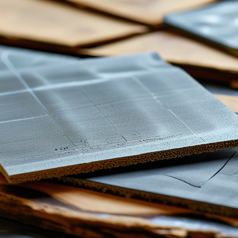
Thermal pads are compliant interface materials placed between a heat source and a heatsink. Their structure usually combines a flexible polymer matrix with thermally conductive fillers. Common fillers include ceramic particles, aluminum oxide, boron nitride, and graphite. Each material changes conductivity, flexibility, electrical behavior, and long-term stability.
Heat moves through the pad by conduction. The pad fills microscopic air gaps caused by rough metal surfaces. Air transfers heat poorly, so replacing it reduces thermal resistance. Thickness matters too. A thicker pad can bridge a larger gap, but it usually adds resistance. Compression also affects contact quality, especially around uneven components. Fit matters.
Global buyers should check thermal conductivity, thermal impedance, hardness, compression range, insulation rating, and operating temperature. Silicone-based pads often offer strong flexibility and reliable gap filling. Non-silicone options may suit sensitive assemblies, but their handling properties can differ. Graphite-based materials can transfer heat efficiently along selected directions, though electrical conductivity requires careful design. Test data deserves attention. Values measured under different pressure or thickness conditions may not compare fairly.
In practical assembly work, I have seen a highly conductive pad perform poorly because it was compressed unevenly. The specification looked impressive. The installation was not. Cut size, surface cleanliness, storage conditions, and fastening pressure can matter just as much. Some assumptions remain incomplete, particularly when real airflow and enclosure limits are ignored. A small prototype test often reveals more than a catalog number.
2026 Top Heatsink Thermal Pad Types for Global Buyers
Key Thermal Pad Types for Heatsink and Component Applications
Silicone gap-filling pads remain common for heatsinks, power modules, memory chips, and voltage regulators. Their softness adapts to uneven surfaces and small assembly gaps. Choose thickness from the measured gap, not from housing dimensions. Excess compression can increase stress on fragile components. Check thermal resistance, hardness, compression range, and electrical insulation data. Measure twice.
Phase-change pads soften during operation and improve contact as temperature rises. They suit processors, power semiconductors, and compact heatsink assemblies with controlled pressure. They usually require a stable mounting force. Without it, performance may vary. A practical test should record temperature before and after thermal cycling. Datasheet values alone can mislead.
Graphite and electrically conductive pads offer strong in-plane heat spreading for selected component designs. They need careful electrical clearance and surface inspection. For irregular gaps, foam-based or reinforced silicone pads may provide better reliability. Thicker materials fill space, but often increase thermal resistance. Not always. Global buyers should also review flame ratings, storage limits, tolerances, and lot consistency. A small thickness variation can change mounting pressure noticeably. My own evaluation would never rely on one sample; repeated testing across several production lots gives a more credible result.
| Thermal Pad Type | Typical Thermal Conductivity | Electrical Property | Typical Hardness | Typical Compressibility | Common Thickness Range | Best-Suited Applications | Main Advantages | Key Limitations | Buyer Selection Priorities |
|---|---|---|---|---|---|---|---|---|---|
| Silicone-Based Thermal Pad | 1.0–8.0 W/m·K | Normally electrically insulating | Shore 00: 20–80 or Shore A: 10–70 | Approximately 10–60% | 0.5–5.0 mm | Power modules, voltage regulators, memory devices, LED assemblies and general heatsink interfaces | Flexible, easy to die-cut, good surface conformity and broad operating-temperature capability | Higher thermal resistance than premium gap fillers at the same thickness; silicone bleed may require evaluation | Balance thermal conductivity, softness, compression force and long-term aging performance |
| Non-Silicone Thermal Pad | 1.5–6.0 W/m·K | Normally electrically insulating | Shore 00: 30–90 or Shore A: 20–80 | Approximately 10–50% | 0.5–5.0 mm | Optical modules, sensors, storage equipment, automotive electronics and contamination-sensitive assemblies | Low silicone contamination risk and suitable for applications requiring cleaner interfaces | May require higher assembly pressure and can be less forgiving of uneven surfaces | Check outgassing, volatile content, compression set and compatibility with optical or coating materials |
| Fiberglass-Reinforced Thermal Pad | 1.0–6.0 W/m·K | Normally electrically insulating | Typically Shore A: 40–90 | Approximately 5–30% | 0.3–3.0 mm | High-volume power supplies, converters, industrial controls and assemblies needing improved handling strength | Better tear resistance, dimensional stability and puncture resistance than unsupported soft pads | Lower conformability; excessive reinforcement can increase contact resistance on rough surfaces | Match reinforcement thickness with surface flatness, mounting pressure and required dielectric strength |
| Graphite Thermal Pad | In-plane: 150–1,500 W/m·K Through-plane: 3–20 W/m·K | Electrically conductive in most constructions | Flexible sheet; hardness is usually not specified like elastomeric pads | Low bulk compression; commonly below 10% | 0.025–0.5 mm | Heat spreading from processors, battery systems, displays and compact electronics with very small gaps | Excellent lateral heat spreading, very thin profile and low material mass | Electrical conductivity, limited gap filling and sensitivity to wrinkles or assembly damage | Confirm electrical isolation, through-plane performance, contact pressure and allowable surface roughness |
| Phase-Change Thermal Pad | 2.0–8.0 W/m·K | Usually electrically insulating; construction-dependent | Solid at room temperature; softens at the specified transition temperature | Low before activation; flows slightly during thermal cycling | 0.05–0.5 mm | CPUs, GPUs, power semiconductors and flat heatsink interfaces requiring low interfacial resistance | Low bond-line thickness and improved wetting after reaching its phase-change temperature | Requires controlled mounting pressure and thermal activation; not ideal for large gaps | Review activation temperature, pump-out resistance, reworkability and surface flatness |
| Aluminum-Filled Thermal Pad | 1.5–6.0 W/m·K | Electrical insulation depends on the polymer matrix and filler design | Typically Shore 00: 40–90 | Approximately 10–45% | 0.5–5.0 mm | Medium-power electronics, motor drives, LED lighting and applications requiring a cost-conscious heat-transfer interface | Good balance of thermal performance, flexibility and material cost | Usually lower conductivity than ceramic-filled premium formulations; filler settling may affect uniformity | Verify dielectric strength, filler distribution, compression set and thermal aging stability |
| Ceramic-Filled Thermal Pad | 3.0–12.0 W/m·K | Normally electrically insulating with high dielectric strength | Typically Shore 00: 40–90 or Shore A: 20–80 | Approximately 10–50% | 0.5–5.0 mm | High-voltage power electronics, inverters, industrial power supplies and automotive control modules | High thermal conductivity combined with electrical insulation and good voltage isolation | Higher cost and potentially higher stiffness than lower-conductivity general-purpose pads | Prioritize dielectric strength, thermal impedance, compression force and qualification under voltage cycling |
| Silicone-Free Gap Filler Pad | 2.0–10.0 W/m·K | Normally electrically insulating | Shore 00: 30–80 | Approximately 20–70% | 1.0–10.0 mm | Battery packs, telecommunications equipment, irregular component stacks and large heatsink-to-enclosure gaps | High gap-filling capability, low contamination risk and good accommodation of dimensional tolerances | Thicker bond lines increase thermal resistance; excessive compression can create mechanical stress | Evaluate compression load, thickness tolerance, sag resistance, flame rating and thermal cycling behavior |
| Adhesive Thermal Pad | 1.0–6.0 W/m·K | Usually electrically insulating; adhesive system must be verified | Varies by carrier and adhesive formulation | Approximately 5–40% | 0.2–2.0 mm | Small heatsinks, LED boards, memory modules and assemblies where mechanical fasteners are unavailable | Combines thermal transfer with attachment and simplifies assembly | Lower reworkability, adhesive aging concerns and potentially higher thermal resistance than clamped interfaces | Check peel strength, shear strength, rework requirements, curing or pressure conditions and service temperature |
| Double-Sided Thermal Interface Pad | 1.0–5.0 W/m·K | Usually electrically insulating; adhesive layers require confirmation | Varies by pad core and adhesive layer | Approximately 10–50% | 0.5–3.0 mm | Compact consumer electronics, enclosure-to-board interfaces and low-load heatsink assemblies | Fast installation, positioning support and reduced need for additional clips or screws | Two adhesive layers add thermal resistance and may reduce serviceability | Assess total thermal impedance, bond durability, surface cleanliness and long-term peel resistance |
| High-Temperature Thermal Pad | 1.0–8.0 W/m·K | Normally electrically insulating; formulation-dependent | Typically Shore 00: 30–90 | Approximately 10–60% | 0.5–5.0 mm | Automotive electronics, industrial drives, outdoor power equipment and high-temperature LED systems | Designed for repeated thermal cycling and elevated continuous operating temperatures | May have higher compression set, greater cost or lower softness than standard formulations | Review continuous-use temperature, short-term peak temperature, compression set and thermal cycling data |
| Flame-Retardant Thermal Pad | 1.0–8.0 W/m·K | Normally electrically insulating | Typically Shore 00: 30–90 | Approximately 10–60% | 0.5–5.0 mm | Power supplies, battery management systems, telecom equipment and safety-regulated electronic products | Supports fire-safety requirements while maintaining thermal and electrical interface functions | Flame-retardant additives can affect softness, surface tack and thermal performance | Confirm the required flammability classification, thickness, dielectric strength and aging performance |
2026 Top Heatsink Thermal Pad Types for Global Buyers
Choosing a thermal pad requires more than comparing conductivity numbers. ASTM D5470 testing measures thermal resistance under defined pressure and temperature. That matters because a pad can show high conductivity yet perform poorly across uneven surfaces. Gap thickness, contact pressure, and surface roughness change the result. Softer silicone pads usually compress more easily around screws and component edges. However, excessive compression can cause material squeeze-out or mechanical stress. A higher conductivity rating is not automatically better.
Electrical insulation needs separate attention. Check dielectric strength, volume resistivity, and thickness after compression. The U.S. Department of Energy reports that cooling can account for up to 40% of data-center electricity use. Efficient heat transfer therefore affects both component reliability and operating cost. Still, thin pads may reduce thermal resistance while weakening insulation margins. This trade-off is often missed during purchasing reviews.
Tips: Request ASTM D5470 data at your expected pressure. Compare thermal resistance, not conductivity alone. Measure pad recovery after repeated compression. Review safety data and compliance documents for each shipment. I have seen designs fail because engineers tested flat laboratory samples, not real heatsinks. That mistake is common, and worth questioning. For global buyers, ask for lot-level thickness tolerance and dielectric test results. Data sheets can look precise, but production variation remains real.
Representative mid-range values for comparing thermal conductivity, compressibility, and electrical insulation. Actual performance depends on thickness, filler content, pressure, surface flatness, and test method.
Higher thermal conductivity improves heat transfer. Higher compressibility helps fill uneven gaps but may reduce mechanical stability. Dielectric strength indicates insulation capability; graphite-based pads are electrically conductive and should not be used where electrical isolation is required.
Thermal pad selection now depends on more than thermal conductivity. The 2024 Fortune Business Insights report valued the global thermal interface materials market at USD 4.03 billion in 2023. It projects USD 7.17 billion by 2030. This growth reflects smaller devices and higher power density. A higher conductivity number is not automatically better. Interface pressure, surface flatness, and long-term compression matter more in many assemblies.
For laptops and compact controllers, thin pads reduce mechanical stress and preserve enclosure space. Power modules may need thicker gap fillers with stronger insulation and lower compression force. In hot, humid climates, check water absorption, aging, and compression set data. In cold regions, verify flexibility during startup. Outdoor equipment also needs suitable flammability performance and stable contact after repeated temperature cycling. IEC 60068-2-78 testing commonly uses 40°C and 93% relative humidity. That condition can expose weak material choices.
Assembly method changes the decision. Die-cut pads suit repeatable high-volume placement. Hand assembly may tolerate softer materials, but alignment becomes inconsistent. Automated lines require clean release liners and predictable thickness. Uneven metal surfaces need conformability, not simply higher conductivity. Field qualification often reveals an uncomfortable truth: laboratory results can overstate real performance. I would compare thermal resistance under actual clamp pressure, then retest after humidity and thermal cycling. Some specifications remain incomplete, and buyers should question them.
Global buyers should treat thermal pads as controlled components, not soft fillers. The International Energy Agency’s Electricity 2024 report estimates data centers used about 415 TWh globally in 2024. Rising density makes interface consistency more important.
Ask for thermal conductivity data measured under ASTM D5470 conditions. Do not accept a single headline value without test pressure, thickness, and temperature. Check compression behavior, dielectric strength, hardness, and long-term aging. A pad that performs at 50% compression may fail inside a thin enclosure. Real assemblies are less tidy.
Compliance needs evidence. Request current RoHS and REACH declarations, material safety data, and restricted-substance test reports from accredited laboratories. For electronics used in equipment, verify applicable safety requirements under IEC 62368-1. Documents should match the exact material grade and production site. Generic certificates create avoidable risk.
Packaging is easy to overlook. Specify moisture barriers, release liners, lot labels, shelf-life dates, and storage limits. Use sealed cartons with clear handling instructions. Suppliers should provide incoming inspection data, batch traceability, dimensional tolerances, and change-notification procedures. The ISO Survey 2023 reports that certified quality-management systems remain widespread across global manufacturing, but certification alone does not prove pad performance. Audit samples from multiple lots. The first sample can be unusually good. That happens.


For those larger-sized parts, or smaller quantity runs, we have 2 independent powder coat booths and ovens. The quality, durability and affordability of today’s powder coating finishes make this the process of choice for world-class companies.
Powder coating advantages over other forms of coating are many. Materials used in the Powder coating process can be metals and non-metals that come in a multitude of thicknesses, textures, colors, etc. Another of Powder coating’s biggest advantages over conventional coatings is its ability to create finishes in many different textures. Powder Coating Booths allow us the ability to apply these advantages to large products.
Tri-State Fabricators runs a full-service conveyor line for painting. Wet painting can provide protection or decoration to many different part styles. From start to finish, every project is easier to undergo random and point-based inspection by our skilled painting team.
Advantages to our Wet Paint Line are these lines start with product prep and ends with a thorough inspection of a high quality finished product. Our ability to complete large and small projects with a superior finish and doing so in a timely and economical fashion. This passes along the savings in production to our customers. When powder coating ins not an option, our Wet Paint Line gets the job done right the first time.
When the parts get big and heavy we roll-out our custom paint racks and oversize booth. By utilizing our partnerships with all the major paint brands, we can match virtually any color with wet paint.
The advantages of having access to a Wet Paint Booth are many. Large projects of many different shapes can be loaded into the booth. The Wet Paint Booth offers an environment that is much more controlled than a typical parts painting operation.
Not only are they used because of their controlled environment, but they’re are also advantageous when it comes to applying paint to parts that are needed in industries that require specialty coatings such as medical, aerospace, etc.
Our military forces have some very high standards when it comes to the finish of their vehicles and equipment. From the first pre-treatment step to final coat, it takes a great deal of knowledge and experience to protect the men and women of our armed forces. They deserve only the best, and Tri-State Fabricators provides it.
All of our processes are closely monitored by our staff and management teams. Both of which are highly trained in the processes of metal fabrication and finishing. Tri-State Fabricators’ goal is to always fully satisfy each and every customer, including the military. We will always put a 110% into what we do.
Abrasive media blasting is an excellent way to remove old paint, rust, and increase the paint/powder adhesion. Glass beads produce a much smoother and brighter finish than angular abrasives; leaving the part clean yet without any dimensional change. Chemically inert and environmentally friendly, we can recycle our beads approximately 30 times; making them a more preferred method of metal cleaning or surface finishing.
Advantages to Glass Bead Blasting are many. Glass bead blast media is used when a project is needing rough surfaces need to become smooth for applications of coatings such as paint. It is typically used to clean paint and rust from a product surface without deforming the surface it is being used on. Overall, compared to many other blasting media, Glass Bead Blasting is a very economical choice and those savings are always passed on to our customers.
Tri-State Fabricators utilize a zinc phosphate wash to clean and etch the material to ensure the best paint adhesion possible. The unique design of our 3-stage wash system does the work like a 5-stage. From Cleaning and rinsing to conversion coating and post-treatment, Our Part Washing process is a complete service and works throughout the fabrication service and the finishing service.
Along with the previously mentioned benefits, Curing is a vital chemical reaction that leaves the product finish hard and relatively safe from mild abrasion and aggressive corrosion. This process can be done in more than one way; ambient air-dry or in curing ovens at temps that exceed 240°.
From fixing paint mistakes (someone else’s of course) to simply cleaning our paint line hooks, our burn-off oven is put to good use. After a quick burn-off, a little clean up, and a fresh coat of paint, your parts will look better than new.
Why does our Burn-Off Oven work so well? Because super heating the air around parts turns the materials into ashes. From paint and powder coatings to rubber and machining oils, high temps do the job without degrading the integrity of the part.
Masking is a vital part of producing high quality products. We have die-cut masking patterns to protect machined surfaces as well as a wide range of plugs and caps to protect threaded holes and bolts. We provide permanent and temporary masking.
Masking allows the selected sections of a product to be protected from a fabrication or finishing service. This can be with both chemicals when etching and tapes, paints when only finishing just a section of the product. Masking is great in aiding the customization process of a project.
Screen printing is a photographic process that transfers artwork onto a porous nylon screen which allows colored ink to flow through the screen and be deposited on an aluminum or plastic component. We can generally have just about any design created onto a screen for your parts.
Some of the advantages of Screen Printing are, brand recognition for your business displaying on your products, assembly instructions, product warnings/hazards, etc. Tri-State Fabricators produces Screen Printing of the highest quality so you know it’s durable.
Metal Finishing is the art of treating the exterior portion of product, often metal but can also be made of other materials, so that the surface is clean and free of any debris. Then the process of applying coats or either paint of powder coat takes place. This coating process improves the quality of the product in both appearance and resistance to wear and corrosion.
Tri-State Fabricators, Inc., understands that a project typically isn’t complete until a high-quality finish has been added to your product. This is why our painting and powder coating teams continuously inspect the products throughout the Metal Finishing process.