


A Battery Management System PCB (BMS PCB) is the control center inside a modern battery pack. It connects sensors, protection circuits, communication interfaces, and power-management components. Together, these parts monitor voltage, current, temperature, and charging conditions. The board may be compact, but its responsibilities are substantial. A weak measurement path can distort the entire safety decision.
Davide Andrea, author of Battery Management Systems for Large Lithium-Ion Battery Packs, describes the BMS as “the brain of the battery pack.” This comparison is useful, although incomplete. The PCB also acts like a nervous system and a safety gate. It collects signals from individual cells, balances charge levels, and can disconnect the pack during abnormal operation. In an electric vehicle, it may monitor dozens or hundreds of cells while communicating with the vehicle controller.
Design details matter. Engineers must consider insulation spacing, heat near switching devices, connector reliability, and electromagnetic interference. A clean schematic does not guarantee a reliable product. Real packs experience vibration, moisture, aging cells, and imperfect assembly. Testing must reflect those conditions.
The topic is not only about circuit diagrams. It concerns measurement accuracy, fault handling, thermal behavior, and serviceability. Even experienced designers can overlook a small failure path. That is why a trustworthy BMS PCB requires documented requirements, controlled production, and repeated validation. Its performance should be judged under normal use and credible fault conditions. The design may never be perfect, but it must fail predictably.
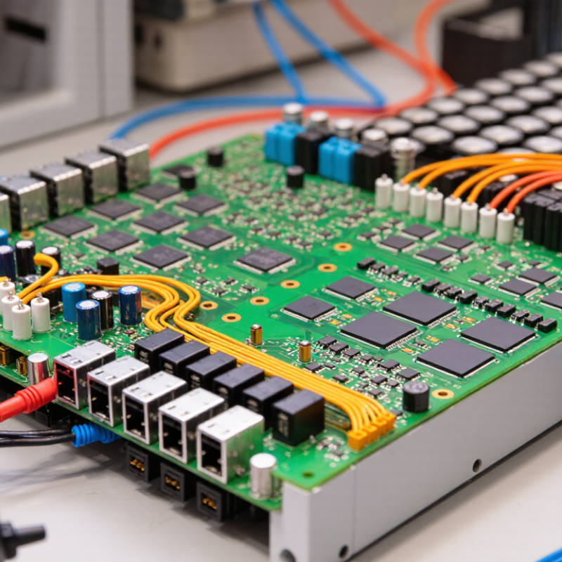
What Is a Battery Management System PCB?
A Battery Management System PCB is the circuit board that monitors and controls a rechargeable battery pack. It connects sensing circuits, protection components, communication interfaces, and the control processor. Its purpose is not simply to “manage” power. It measures each cell’s voltage, pack current, and temperature during charging and discharging.
When a cell reaches an unsafe limit, the PCB can interrupt the circuit through electronic switches. It may also balance cells by removing small amounts of excess energy from stronger cells. This keeps cell voltages closer together. A reliable design reduces overcharging, deep discharge, overheating, and unexpected shutdowns. Small details matter. A misplaced temperature sensor can delay a protective response.
The PCB also provides useful information to external equipment. It can report remaining capacity, fault conditions, charge cycles, and operating temperature. In a practical inspection, engineers check connector strength, copper trace width, insulation spacing, and test points. They also verify sensor accuracy under changing loads. A schematic may look correct but still fail during vibration, heat, or sudden current demand. That is why prototypes need repeated electrical and environmental testing. Some designs require careful calibration after assembly, and this step is sometimes underestimated. The board must fit the battery enclosure while handling heat, moisture, and manufacturing variation. Safety depends on both circuit logic and physical execution.
A battery management system PCB controls, monitors, and protects rechargeable battery packs. Its circuit architecture usually has separate sensing, control, power, and communication sections. This separation reduces noise and makes fault diagnosis easier.
The cell-monitoring circuit measures each cell’s voltage through carefully matched resistors. Thermistors track temperature near cells, busbars, and charging paths. A microcontroller processes these readings and compares them with safety limits.
Current sensing uses a shunt resistor or magnetic sensor. Power MOSFETs then control charging and discharging. Passive or active balancing circuits correct cell differences, although balancing can waste energy in simpler designs.
Communication interfaces transmit status data to external equipment. Isolation may be necessary when voltage levels or system grounds differ.
Good layouts keep high-current copper paths short and wide. Sensitive measurement traces should stay away from switching nodes. Designers often add fuses, transient protection, and redundant temperature checks. In practice, perfect balance is difficult. Connector resistance, aging cells, and uneven cooling can distort measurements. A reliable PCB should detect these imperfections, not hide them.
Place test points beside cell-sense inputs and temperature channels. Validate the board with controlled fault tests, including open wires, shorted sensors, and overheated cells. Review creepage distances before production. A small layout shortcut can create a serious measurement error.
What Is a Battery Management System PCB?
A BMS PCB is the battery pack’s measurement and decision layer. It monitors each cell rather than treating the pack as one large battery. Voltage-sensing channels sample cell voltage through an analog front end, while thermistors track temperature near cells, busbars, and charging paths. A current shunt or Hall sensor measures charge and discharge flow. The controller then estimates state of charge and state of health.
Protection is active, not decorative. If one cell exceeds its voltage limit, the PCB can stop charging through control switches or a contactor. It can also disconnect the load during overcurrent, short-circuit, or abnormal temperature events. Passive balancing bleeds small currents from higher-voltage cells; active systems redistribute energy, but they add complexity. The IEA’s Global EV Outlook 2024 reported about 750 GWh of battery demand in the energy sector during 2023, showing why dependable cell-level monitoring matters. BloombergNEF reported an average lithium-ion battery pack price of 115 USD per kWh in 2024, down 20% year over year. Lower costs do not remove design risk.
A BMS PCB is not a magic shield. Sensor placement, calibration drift, connector resistance, and poor firmware limits can still produce unsafe decisions. Field engineers should verify readings with independent instruments and review fault logs under real thermal conditions. One overlooked detail: a cold sensor may look normal while a nearby cell develops a hot spot. That deserves more skepticism.
What Is a Battery Management System PCB?
A Battery Management System PCB is the control layer inside a battery pack. It measures cell voltage, current, and temperature through dedicated sensing circuits. The board also controls charging, discharging, contactors, and fault isolation. In electric vehicles, this work is becoming more demanding. The International Energy Agency reported that global electric-car battery demand exceeded 750 GWh in 2023, rising by about 40% from 2022. More cells mean more measurement points and more opportunities for imbalance.
Balancing methods shape pack reliability. Passive balancing uses resistors to bleed excess energy from higher-voltage cells. It is simple and inexpensive, but the wasted energy becomes heat. Active balancing transfers energy between cells through inductors or capacitors. This approach can improve usable capacity, though its circuitry and control logic are harder to validate. In practice, the PCB should balance only when voltage differences, temperature, and charging conditions are safe. A fixed threshold alone may be too crude.
Pack control is more than voltage checking. The PCB estimates state of charge and state of health, then limits current when cells approach unsafe conditions. It can open a protection path within milliseconds after detecting a short circuit or abnormal temperature. BloombergNEF reported an average lithium-ion battery pack price of 139 dollars per kWh in 2023, showing why efficient control matters economically. Still, estimates drift. Sensor errors, aging, and uneven cooling can mislead the algorithm. Engineers should test real cells, not only ideal simulations. That lesson is easy to overlook.
| BMS PCB Function | What It Monitors or Controls | Typical Implementation | Key Benefit | Important Design Consideration | Relevant Battery-Pack Data |
|---|---|---|---|---|---|
| Cell Voltage Monitoring | Individual cell voltage, total pack voltage, and voltage deviation between cells. | Dedicated cell-monitoring inputs connected through a resistor-divider and filtering network. | Detects overvoltage, undervoltage, imbalance, and abnormal cell behavior. | Measurement accuracy, input filtering, creepage distance, and isolation requirements must match the pack voltage. | Lithium-ion cells commonly operate around 2.5–4.2 V per cell, depending on chemistry and operating limits. |
| Temperature Monitoring | Cell, busbar, power-switch, charger, and enclosure temperatures. | Negative temperature coefficient thermistors or digital temperature sensors placed near heat sources. | Helps prevent charging or discharging outside safe temperature limits. | Sensor placement and thermal coupling are as important as sensor accuracy. | Many lithium-ion systems restrict charging near or below 0°C because lithium plating can occur, while the exact limits depend on cell design. |
| Passive Balancing | Excess charge stored in higher-voltage cells. | A resistor and switching device discharge selected cells into heat. | Simple architecture, low component count, and relatively low cost. | Balancing current is limited by resistor power, heat dissipation, and PCB spacing. | A 100 Ω balancing resistor at 4.0 V draws approximately 40 mA and dissipates approximately 0.16 W. |
| Active Balancing | Charge difference between cells or cell groups. | Inductors, capacitors, transformers, or switched converters transfer energy from higher-state cells to lower-state cells. | Reduces energy loss and can support faster balancing in larger battery packs. | Requires more components, control logic, electromagnetic compatibility management, and fault protection. | Energy-transfer efficiency varies with topology, switching frequency, current level, and cell-voltage difference. |
| Overvoltage Protection | Cell voltage during charging and regeneration. | The BMS reduces or interrupts charging through a charge-control switch, contactor, or charger communication link. | Prevents cell damage caused by excessive charging voltage. | Protection thresholds must account for measurement tolerance, temperature, response time, and cell chemistry. | For many conventional lithium-ion cells, the upper charge limit is approximately 4.2 V per cell, but the specified value is chemistry-dependent. |
| Undervoltage Protection | Cell voltage during discharge and standby. | The BMS disconnects the load or commands the system to reduce power when a cell reaches its lower limit. | Limits over-discharge, which can permanently reduce capacity or create safety concerns. | Load transients and voltage recovery after current removal should be considered to avoid nuisance shutdowns. | Typical lower operating limits for lithium-ion cells may be near 2.5–3.0 V per cell, depending on the cell specification. |
| Overcurrent and Short-Circuit Protection | Charge current, discharge current, and sudden current spikes. | Current-sense resistor, Hall-effect sensor, fuse, MOSFETs, or contactors. | Protects cells, conductors, switching devices, and loads from excessive current. | Detection delay, sensor bandwidth, fuse coordination, and MOSFET safe operating area are critical. | Allowable current is determined by cell rating, thermal conditions, conductor size, and system duty cycle. |
| State of Charge Estimation | Remaining usable charge, usually expressed as a percentage. | Coulomb counting combined with voltage, current, temperature, and model-based corrections. | Provides useful remaining-runtime and charging information. | Current-sensor offset, capacity aging, temperature, and initialization errors affect accuracy. | State of charge is an estimate rather than a direct measurement and normally requires periodic correction. |
| State of Health Estimation | Capacity loss, resistance increase, and performance degradation over time. | Analysis of charge-discharge history, usable capacity, voltage response, and internal-resistance trends. | Supports maintenance decisions, warranty analysis, and safe end-of-life management. | Reliable estimation requires sufficient operating history and controlled reference conditions. | Capacity fade and resistance growth are influenced by temperature, current rate, depth of discharge, and storage conditions. |
| Charge and Discharge Control | Whether the battery may accept or deliver current. | Back-to-back MOSFETs, relays, contactors, pre-charge circuits, or system-level communication. | Provides controlled connection and disconnection of the battery pack. | Switch voltage rating, conduction loss, inrush current, isolation, and fail-safe behavior must be evaluated. | Pre-charge limits the transient current used to charge capacitors in the load before the main connection is closed. |
| Communication and Diagnostics | Measured values, alarms, fault codes, limits, and operating status. | Common wired interfaces include CAN, UART, SMBus, or isolated communication links. | Enables charger coordination, vehicle or equipment control, service diagnostics, and event logging. | Message integrity, isolation, cybersecurity, connector reliability, and fault handling should be defined. | Typical diagnostic data includes minimum and maximum cell voltage, pack current, temperature range, state of charge, and active faults. |
| PCB Power and Signal Integrity | Low-voltage logic power, high-current paths, analog measurement signals, and switching noise. | Separate analog and power areas, controlled grounding, filtering, thermal vias, and appropriately sized copper. | Improves measurement stability, thermal performance, and overall reliability. | High-current traces must be sized for temperature rise, while sensitive measurement paths should be routed away from switching nodes. | Trace capability depends on copper thickness, trace width, allowable temperature rise, airflow, and conductor length. |
| Safety and Fault Management | Sensor faults, welded switches, open wires, communication loss, isolation faults, and abnormal voltage patterns. | Redundant checks, watchdog timers, hardware comparators, fuses, isolation monitoring, and defined safe-state logic. | Reduces the likelihood that a single component failure will create an uncontrolled battery condition. | Protection should be layered so that software, hardware, and external protective devices complement one another. | Safety limits and response times must be validated through fault-injection testing and pack-level verification. |
What Is a Battery Management System PCB?
A Battery Management System PCB monitors, protects, and controls rechargeable battery packs. It measures cell voltage, current, temperature, and charging conditions in real time. Engineers use it in electric vehicles, energy storage units, portable equipment, and backup power systems. The board can disconnect the pack during overvoltage, deep discharge, overheating, or short-circuit events.
Design factors depend on the battery chemistry and pack structure. A lithium-ion pack with twelve series cells needs accurate voltage sensing and reliable cell balancing. Current measurement must support both normal operation and sudden load changes. Thermal sensors should sit near heat-producing cells, connectors, and power switches. The PCB also needs suitable creepage distances, insulation, grounding, and communication interfaces. Safety standards vary by product and market. Designers may evaluate requirements from IEC 62133, UL 2271, IEC 62619, or related regional rules. Compliance is not achieved by the PCB alone; testing, enclosure design, firmware, and production controls also matter. A prototype can pass bench tests and still fail under vibration or cold conditions.
Tips: Keep sensing traces short and separated from high-current paths. Test balancing at low and high temperatures. Record fault events for service analysis. Do not trust a single sensor. One overlooked connector can weaken the whole system. Review protection thresholds with real load profiles, not only ideal calculations. Some design decisions remain uncertain until field testing reveals unexpected heating, noise, or user behavior.
A battery management system PCB estimates state of charge by combining cell-voltage, current, and temperature measurements. The curve below represents typical open-circuit voltage behavior for a lithium-ion cell at room temperature; actual values vary with chemistry, temperature, load history, and aging.
BMS PCB designs commonly include cell balancing, overvoltage and undervoltage protection, overcurrent detection, thermal monitoring, and communication interfaces. Relevant safety frameworks may include IEC 62619 for industrial lithium secondary batteries, IEC 62133 for portable applications, UL 1973 for stationary and auxiliary battery systems, and UN 38.3 for transport testing.


For those larger-sized parts, or smaller quantity runs, we have 2 independent powder coat booths and ovens. The quality, durability and affordability of today’s powder coating finishes make this the process of choice for world-class companies.
Powder coating advantages over other forms of coating are many. Materials used in the Powder coating process can be metals and non-metals that come in a multitude of thicknesses, textures, colors, etc. Another of Powder coating’s biggest advantages over conventional coatings is its ability to create finishes in many different textures. Powder Coating Booths allow us the ability to apply these advantages to large products.
Tri-State Fabricators runs a full-service conveyor line for painting. Wet painting can provide protection or decoration to many different part styles. From start to finish, every project is easier to undergo random and point-based inspection by our skilled painting team.
Advantages to our Wet Paint Line are these lines start with product prep and ends with a thorough inspection of a high quality finished product. Our ability to complete large and small projects with a superior finish and doing so in a timely and economical fashion. This passes along the savings in production to our customers. When powder coating ins not an option, our Wet Paint Line gets the job done right the first time.
When the parts get big and heavy we roll-out our custom paint racks and oversize booth. By utilizing our partnerships with all the major paint brands, we can match virtually any color with wet paint.
The advantages of having access to a Wet Paint Booth are many. Large projects of many different shapes can be loaded into the booth. The Wet Paint Booth offers an environment that is much more controlled than a typical parts painting operation.
Not only are they used because of their controlled environment, but they’re are also advantageous when it comes to applying paint to parts that are needed in industries that require specialty coatings such as medical, aerospace, etc.
Our military forces have some very high standards when it comes to the finish of their vehicles and equipment. From the first pre-treatment step to final coat, it takes a great deal of knowledge and experience to protect the men and women of our armed forces. They deserve only the best, and Tri-State Fabricators provides it.
All of our processes are closely monitored by our staff and management teams. Both of which are highly trained in the processes of metal fabrication and finishing. Tri-State Fabricators’ goal is to always fully satisfy each and every customer, including the military. We will always put a 110% into what we do.
Abrasive media blasting is an excellent way to remove old paint, rust, and increase the paint/powder adhesion. Glass beads produce a much smoother and brighter finish than angular abrasives; leaving the part clean yet without any dimensional change. Chemically inert and environmentally friendly, we can recycle our beads approximately 30 times; making them a more preferred method of metal cleaning or surface finishing.
Advantages to Glass Bead Blasting are many. Glass bead blast media is used when a project is needing rough surfaces need to become smooth for applications of coatings such as paint. It is typically used to clean paint and rust from a product surface without deforming the surface it is being used on. Overall, compared to many other blasting media, Glass Bead Blasting is a very economical choice and those savings are always passed on to our customers.
Tri-State Fabricators utilize a zinc phosphate wash to clean and etch the material to ensure the best paint adhesion possible. The unique design of our 3-stage wash system does the work like a 5-stage. From Cleaning and rinsing to conversion coating and post-treatment, Our Part Washing process is a complete service and works throughout the fabrication service and the finishing service.
Along with the previously mentioned benefits, Curing is a vital chemical reaction that leaves the product finish hard and relatively safe from mild abrasion and aggressive corrosion. This process can be done in more than one way; ambient air-dry or in curing ovens at temps that exceed 240°.
From fixing paint mistakes (someone else’s of course) to simply cleaning our paint line hooks, our burn-off oven is put to good use. After a quick burn-off, a little clean up, and a fresh coat of paint, your parts will look better than new.
Why does our Burn-Off Oven work so well? Because super heating the air around parts turns the materials into ashes. From paint and powder coatings to rubber and machining oils, high temps do the job without degrading the integrity of the part.
Masking is a vital part of producing high quality products. We have die-cut masking patterns to protect machined surfaces as well as a wide range of plugs and caps to protect threaded holes and bolts. We provide permanent and temporary masking.
Masking allows the selected sections of a product to be protected from a fabrication or finishing service. This can be with both chemicals when etching and tapes, paints when only finishing just a section of the product. Masking is great in aiding the customization process of a project.
Screen printing is a photographic process that transfers artwork onto a porous nylon screen which allows colored ink to flow through the screen and be deposited on an aluminum or plastic component. We can generally have just about any design created onto a screen for your parts.
Some of the advantages of Screen Printing are, brand recognition for your business displaying on your products, assembly instructions, product warnings/hazards, etc. Tri-State Fabricators produces Screen Printing of the highest quality so you know it’s durable.
Metal Finishing is the art of treating the exterior portion of product, often metal but can also be made of other materials, so that the surface is clean and free of any debris. Then the process of applying coats or either paint of powder coat takes place. This coating process improves the quality of the product in both appearance and resistance to wear and corrosion.
Tri-State Fabricators, Inc., understands that a project typically isn’t complete until a high-quality finish has been added to your product. This is why our painting and powder coating teams continuously inspect the products throughout the Metal Finishing process.