


7 Tips for Choosing Motor Soft Starters 380V to 10kV

Selecting a motor starter is rarely a simple voltage-matching exercise. A 380V pump and a 10kV compressor can share the same starting problem, but their risks differ sharply. Inrush current, mechanical load, cable length, and fault levels all influence the decision.

This guide examines seven practical tips for choosing motor soft starters 380v to 10kv. It reflects common engineering checks used on industrial sites, including nameplate verification, starting-torque assessment, and thermal-duty review. A reliable selection begins with accurate field information. Record the motor rating, rated current, acceleration time, load inertia, and number of starts per hour. Small details matter.

Think beyond the catalog page.

A soft starter may reduce voltage stress, but it cannot correct an undersized transformer or a poorly aligned pump. Medium-voltage systems also require careful insulation coordination, bypass arrangements, protection settings, and qualified commissioning. Manufacturer data should be compared with the actual motor and driven equipment, not copied from a similar project. That shortcut often creates avoidable delays.

The most useful choice balances electrical performance, mechanical protection, maintenance access, and total operating cost. For example, a conveyor needing smooth acceleration may require different settings from a centrifugal fan with a light starting load. Site temperature and enclosure conditions can also change expected performance. No selection is perfect without verification. Even experienced engineers should challenge their assumptions before energizing equipment. These seven tips provide a practical framework for making that review more consistent, traceable, and dependable.
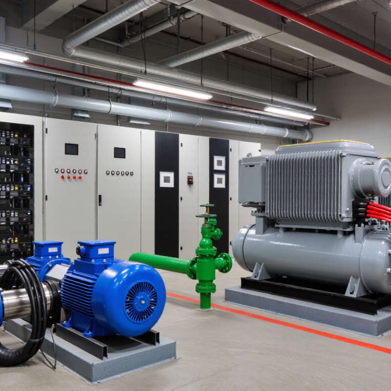
7 Tips for Choosing Motor Soft Starters 380V to 10kV

Voltage-Class Selection: 380 V Low-Voltage to 10 kV Medium-Voltage Systems

Choosing a motor soft starter from 380 V to 10 kV begins with the motor’s actual voltage class, not the label alone. A 380 V starter usually serves low-voltage motors in pumps, fans, and conveyors. Medium-voltage systems commonly use 3.3 kV, 6 kV, or 10 kV equipment. These ranges require different insulation, clearances, switching devices, and test procedures. A neat voltage label can mislead.

For a 380 V installation, check rated current, locked-rotor current, enclosure heat, and bypass contactor duty. Cable length and frequent starts can change thermal performance. In a 6 kV or 10 kV plant, review insulation coordination, surge protection, dielectric tests, grounding, and arc-resistant construction. The starter must match the motor terminals and upstream fault level. IEC-based documentation helps, but project drawings and local electrical rules still require verification.

Practical commissioning should record starting time, current decay, motor voltage, and mechanical vibration. A pump may need controlled torque, while a crusher may demand more starting capability than a simple current limit provides. Ask about service access, bypass behavior, cooling, and spare thyristor modules. Field checks often reveal mismatched CT ratios or incomplete interlocks. That mistake is easy to miss. If the application remains uncertain, measure the load before selecting the voltage class.

Motor and Load Matching: Starting Current Commonly Reaches 5–8× Full-Load Current

Choosing a motor soft starter from 380 V to 10 kV begins with motor-load matching, not voltage alone.

A squirrel-cage motor commonly draws 5–8 times full-load current during direct-on-line starting. This range aligns with locked-rotor guidance in NEMA MG 1 and the U.S. Department of Energy’s motor-system sourcebook. The figure is not a setting. Confirm nameplate current, locked-rotor code, starting torque, and permitted starts per hour.

Pump, fan, compressor, and conveyor loads behave differently. A centrifugal pump usually needs rising torque, while a loaded conveyor may demand near-full torque at zero speed. Select a starter for actual acceleration current and time, not only motor kW.

Check voltage drop at the supply bus. IEEE 141 recommends studying motor-starting voltage dips when large motors share a feeder. A 6.6 kV motor can still trip protection if the source is weak.

Measure the load. Do not guess.

Review thyristor thermal limits, bypass duty, cable length, protection settings, and ambient temperature. IEC 60947-4-1 provides useful low-voltage starter requirements, while medium-voltage projects need coordinated switchgear and insulation studies. In field commissioning, a short ramp can leave a high-current spike; a long ramp can overheat the motor. The spreadsheet may look correct, yet the conveyor may be jammed with material. Recheck inertia, friction, and restart conditions before final selection.

Ramp-Time and Torque Control: Motor Torque Varies Approximately With Voltage²

Selecting a motor soft starter from 380V to 10kV begins with the load, not the voltage label. The U.S. Department of Energy’s 2021 Motor Systems Market Assessment reports that motor-driven equipment consumes about 68% of U.S. manufacturing electricity. Small control errors can therefore become expensive. Check rated current, motor starting torque, duty cycle, enclosure conditions, bypass requirements, and short-circuit ratings. Also confirm whether the starter suits pumps, conveyors, compressors, or high-inertia fans.

Ramp time needs practical judgment. Motor torque varies approximately with voltage². At 80% voltage, available starting torque may fall to about 64% of its full-voltage value. That reduction can protect couplings, but it may stall a loaded conveyor. A 20-second ramp is not automatically gentle. It can overheat the motor when acceleration remains incomplete. Measure acceleration time, current, and shaft response on site. Do not trust settings alone.

The International Energy Agency’s Energy Efficiency Market Report 2016 indicates that electric motor systems consume nearly half of global electricity. Efficient starting is therefore an operating issue, not merely an installation detail. Compare soft starters by voltage-control accuracy, thermal capacity, bypass performance, harmonic behavior, and fault logging. For medium-voltage systems, inspect insulation coordination and maintenance access carefully. I would also leave engineering margin for cold oil, sticky bearings, or seasonal process changes. That assumption may be imperfect. Real loads often disagree with commissioning calculations.

Protection and Bypass Verification Under IEC 60947-4-1 Requirements

Choosing a motor soft starter from 380V to 10kV requires more than checking the motor’s rated current. Verify the starter’s operating category, overload settings, short-circuit coordination, and duty cycle. IEC 60947-4-1 provides a useful framework for low-voltage contactors and motor-starters. At 380V, confirm the device rating matches the motor’s utilization category and starting frequency.

Protection must remain active during acceleration and stopping. Test phase-loss detection, overcurrent response, locked-rotor protection, thermal modeling, and bypass transfer logic. The bypass contactor should close only after the motor reaches stable speed. Check its making and breaking capacity under the actual load. A poorly timed bypass can create a severe current surge.

This deserves attention.

For systems near 10kV, IEC 60947-4-1 alone may not cover every medium-voltage requirement. Review the applicable medium-voltage switchgear standards, insulation levels, clearances, and enclosure tests. Confirm withstand performance through documented factory and site testing. Inspect cable terminations, grounding continuity, interlocks, and emergency stop behavior. Record trip thresholds and measured transfer times.

Field experience shows that commissioning teams sometimes test protection separately, then skip combined bypass trials. That approach leaves a gap. Test normal starts, repeated starts, blocked-rotor conditions, supply interruptions, and failed bypass commands. I would also question default settings, even when they appear conservative. The motor, driven load, transformer, and upstream protection must be evaluated as one system.

7 Tips for Choosing Motor Soft Starters 380V to 10kV — Protection and Bypass Verification Under IEC 60947-4-1 Requirements
Tip Selection Dimension Recommended Engineering Check Typical Data or Range Protection and Bypass Verification Acceptance Evidence
1 Match the system voltage and motor rating Confirm the motor rated voltage, frequency, phase arrangement, insulation level, available fault current, and the soft starter's rated operational voltage. Low-voltage systems commonly use 380 V, 400 V, or 415 V at 50 Hz. Medium-voltage applications commonly use 3.3 kV, 6.6 kV, or 10 kV. The starter voltage rating must not be lower than the system voltage. Verify phase-to-phase voltage withstand, power-frequency withstand, clearances, creepage distances, enclosure requirements, and suitable upstream short-circuit protection. Approved single-line diagram, nameplate comparison, insulation test record, dielectric-test certificate, and short-circuit coordination study.
2 Size by motor current and starting duty Select the starter from the motor nameplate full-load current and the actual starting profile rather than from horsepower or kilowatt rating alone. The continuous current rating should be at least equal to the motor full-load current. Check the number of starts per hour, starting duration, load torque, ambient temperature, altitude, and enclosure derating. Confirm that the overload model, current transformers, semiconductor thermal limits, and bypass contactor duty are suitable for the complete start-and-run cycle. Motor data sheet, load-torque calculation, thermal-duty calculation, manufacturer-neutral rating schedule, and recorded starting-current trend.
3 Choose a suitable acceleration strategy Select voltage ramp, current limit, torque control, or pump-specific ramping according to the driven load and the required mechanical acceleration. A current-limit setting of approximately 2 to 4 times motor full-load current is often used as an initial commissioning range, but the final value must be confirmed by motor torque and load requirements. Verify that the motor reaches rated speed without a stall trip, excessive voltage depression, water hammer, belt shock, coupling stress, or repeated thermal overload. Start-current waveform, acceleration time, motor terminal-voltage record, vibration observation, and final parameter sheet.
4 Specify complete motor protection Define which protection functions are integrated into the starter and which must be supplied by external relays, circuit breakers, fuses, or motor protection systems. Common functions include electronic overload, phase loss, phase unbalance, phase sequence, under- and overvoltage, locked rotor or stall, excessive starts, heatsink overtemperature, and control-supply failure. Confirm trip thresholds, time delays, reset behavior, fail-safe operation, alarm contacts, and coordination with upstream short-circuit and earth-fault protection. Do not assume every function is built in. Protection setting list, coordination study, trip simulation results, alarm contact test, and documented reset or restart logic.
5 Verify the bypass arrangement Determine whether the bypass is internal or external and confirm that it closes only after the motor has completed acceleration and the semiconductor path is ready to be released. A bypass contactor should be rated for the motor's running current and selected for the actual switching duty. AC-3 is relevant when a contactor makes or breaks squirrel-cage motor current; the applicable utilization category must be confirmed for the circuit duty. Test bypass close timing, auxiliary-contact interlocking, failure-to-close alarm, failure-to-open behavior, contact welding detection where provided, and automatic transfer back to semiconductor control after a bypass fault. Bypass wiring diagram, contactor utilization-category data, interlock test, measured transfer sequence, and thermal comparison before and after bypass operation.
6 Check thermal performance and installation conditions Calculate heat dissipation during starting and running, including whether the bypass is closed during normal operation. Review ventilation, cabinet spacing, altitude, ambient temperature, and harmonic effects. Semiconductor losses are highest while the motor current flows through the thyristors. A correctly operating bypass substantially reduces continuous starter losses, but it does not remove the need to verify starting thermal duty. Verify heatsink temperature, fan or ventilation status, cabinet temperature rise, temperature-trip operation, and safe behavior if the bypass does not close. Temperature-rise calculation, cabinet thermal test, fan-failure simulation, temperature alarm test, and installation inspection report.
7 Perform a documented IEC-based verification Separate the requirements for the semiconductor soft starter from those for the associated contactor, motor starter, enclosure, protective device, and control circuit. IEC 60947-4-1 applies to electromechanical contactors and motor-starters. Semiconductor motor controllers and starters are generally covered by IEC 60947-4-2, so the project specification should identify both standards where both device types are used. Conduct FAT and site tests for insulation, protective-earth continuity, phase sequence, start and stop commands, current limit, overload, phase loss, emergency stop, bypass transfer, bypass failure, and restart inhibition. Signed inspection and test plan, factory test report, commissioning records, protection-trip records, as-built drawings, and final parameter backup.
Standards note: IEC 60947-4-1 covers electromechanical contactors and motor-starters, while IEC 60947-4-2 specifically addresses semiconductor motor controllers and starters. For a soft-starter package with an electromechanical bypass contactor, verify the applicable requirements for each component and for their complete assembly.

Harmonics, Duty Rating, Environment, and Lifecycle Cost Assessment

Choosing a motor soft starter from 380V to 10kV requires more than matching voltage and motor power. Harmonic behavior can affect transformers, protection devices, and nearby control equipment. Ask for measured current distortion, not only brochure values. Check performance during acceleration, bypass operation, and lightly loaded running.

Measure it on site.

Duty rating is equally important. Record the motor’s starting current, load inertia, starts per hour, and expected daily operating cycle. A pump starting twice daily has different thermal demands from a crusher starting every few minutes. Confirm the starter’s continuous current, overload profile, and cooling method. Incorrect duty assumptions can shorten service life. I have seen projects fail because “normal duty” was interpreted too generously.

Environment changes the calculation. Review ambient temperature, altitude, dust, humidity, enclosure rating, and ventilation space. Medium-voltage equipment may need wider clearances or derating at high elevations. Lifecycle cost should include energy losses, cooling power, inspections, spare parts, commissioning, and production downtime. A cheaper unit can become expensive after repeated nuisance trips. A spreadsheet can mislead. Use measured operating data where possible, and include realistic maintenance labor. Verify applicable electrical standards and protection coordination with a qualified engineer before installation.

Powder Coat Booths

For those larger-sized parts, or smaller quantity runs, we have 2 independent powder coat booths and ovens. The quality, durability and affordability of today’s powder coating finishes make this the process of choice for world-class companies.

Powder coating advantages over other forms of coating are many. Materials used in the Powder coating process can be metals and non-metals that come in a multitude of thicknesses, textures, colors, etc. Another of Powder coating’s biggest advantages over conventional coatings is its ability to create finishes in many different textures. Powder Coating Booths allow us the ability to apply these advantages to large products.

Wet Paint Line

Tri-State Fabricators runs a full-service conveyor line for painting. Wet painting can provide protection or decoration to many different part styles. From start to finish, every project is easier to undergo random and point-based inspection by our skilled painting team.

Advantages to our Wet Paint Line are these lines start with product prep and ends with a thorough inspection of a high quality finished product. Our ability to complete large and small projects with a superior finish and doing so in a timely and economical fashion. This passes along the savings in production to our customers. When powder coating ins not an option, our Wet Paint Line gets the job done right the first time.

Wet Paint Booths

When the parts get big and heavy we roll-out our custom paint racks and oversize booth. By utilizing our partnerships with all the major paint brands, we can match virtually any color with wet paint.

The advantages of having access to a Wet Paint Booth are many. Large projects of many different shapes can be loaded into the booth. The Wet Paint Booth offers an environment that is much more controlled than a typical parts painting operation.

Not only are they used because of their controlled environment, but they’re are also advantageous when it comes to applying paint to parts that are needed in industries that require specialty coatings such as medical, aerospace, etc.

Military CARC

Our military forces have some very high standards when it comes to the finish of their vehicles and equipment. From the first pre-treatment step to final coat, it takes a great deal of knowledge and experience to protect the men and women of our armed forces. They deserve only the best, and Tri-State Fabricators provides it.

All of our processes are closely monitored by our staff and management teams. Both of which are highly trained in the processes of metal fabrication and finishing. Tri-State Fabricators’ goal is to always fully satisfy each and every customer, including the military. We will always put a 110% into what we do.

Glass-Bead Blasting

Abrasive media blasting is an excellent way to remove old paint, rust, and increase the paint/powder adhesion. Glass beads produce a much smoother and brighter finish than angular abrasives; leaving the part clean yet without any dimensional change. Chemically inert and environmentally friendly, we can recycle our beads approximately 30 times; making them a more preferred method of metal cleaning or surface finishing.

Advantages to Glass Bead Blasting are many. Glass bead blast media is used when a project is needing rough surfaces need to become smooth for applications of coatings such as paint. It is typically used to clean paint and rust from a product surface without deforming the surface it is being used on. Overall, compared to many other blasting media, Glass Bead Blasting is a very economical choice and those savings are always passed on to our customers.

Part Washing

Tri-State Fabricators utilize a zinc phosphate wash to clean and etch the material to ensure the best paint adhesion possible. The unique design of our 3-stage wash system does the work like a 5-stage. From Cleaning and rinsing to conversion coating and post-treatment, Our Part Washing process is a complete service and works throughout the fabrication service and the finishing service.

Along with the previously mentioned benefits, Curing is a vital chemical reaction that leaves the product finish hard and relatively safe from mild abrasion and aggressive corrosion. This process can be done in more than one way; ambient air-dry or in curing ovens at temps that exceed 240°.

Burn-Off Oven

From fixing paint mistakes (someone else’s of course) to simply cleaning our paint line hooks, our burn-off oven is put to good use. After a quick burn-off, a little clean up, and a fresh coat of paint, your parts will look better than new.

Why does our Burn-Off Oven work so well? Because super heating the air around parts turns the materials into ashes. From paint and powder coatings to rubber and machining oils, high temps do the job without degrading the integrity of the part.

Masking

Masking is a vital part of producing high quality products. We have die-cut masking patterns to protect machined surfaces as well as a wide range of plugs and caps to protect threaded holes and bolts. We provide permanent and temporary masking.

Masking allows the selected sections of a product to be protected from a fabrication or finishing service. This can be with both chemicals when etching and tapes, paints when only finishing just a section of the product. Masking is great in aiding the customization process of a project.

Screen Printing

Screen printing is a photographic process that transfers artwork onto a porous nylon screen which allows colored ink to flow through the screen and be deposited on an aluminum or plastic component. We can generally have just about any design created onto a screen for your parts.

Some of the advantages of Screen Printing are, brand recognition for your business displaying on your products, assembly instructions, product warnings/hazards, etc. Tri-State Fabricators produces Screen Printing of the highest quality so you know it’s durable.

Metal Finishing

Metal Finishing is the art of treating the exterior portion of product, often metal but can also be made of other materials, so that the surface is clean and free of any debris. Then the process of applying coats or either paint of powder coat takes place. This coating process improves the quality of the product in both appearance and resistance to wear and corrosion.

Tri-State Fabricators, Inc., understands that a project typically isn’t complete until a high-quality finish has been added to your product. This is why our painting and powder coating teams continuously inspect the products throughout the Metal Finishing process.