


What Is an MCB Insulation Tester and How Does It Work?

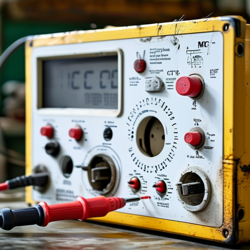
A Mcb Insulation Tester is a practical instrument for checking whether insulation can safely contain electrical voltage. It applies a controlled DC test voltage across an isolated circuit. The tester then measures leakage current and converts it into insulation resistance, usually shown in megohms. High resistance generally indicates healthier insulation. Low resistance demands investigation.

This matters because small defects can hide behind a clean-looking MCB. Heat, moisture, dust, loose terminals, and aged cable jackets may create invisible leakage paths. IEC 60364-6:2016 includes insulation resistance verification within electrical installation testing. NFPA 70B:2023 also emphasizes documented maintenance, qualified personnel, and condition-based evaluation. These standards do not make testing automatic. The test method still matters.

Electrical-safety author John Cadick offers a useful reminder: “A test result is only as good as the method behind it.” His point is especially relevant here. An MCB Insulation Tester must be used on a properly isolated, de-energized circuit. Sensitive electronics may require disconnection before testing. Afterward, stored charge must be discharged safely. Never treat one reading as the complete diagnosis.

This guide explains the instrument’s internal process, test voltages, resistance readings, and safe operating sequence. It also examines common mistakes, including testing connected equipment and ignoring temperature effects. The explanation is intentionally practical. Real panels are not laboratory-perfect. Readings can drift. Human judgment remains essential. That is the part many short guides miss.
What Is an MCB Insulation Tester and How Does It Work?

Definition and Purpose of an MCB Insulation Tester

What Is an MCB Insulation Tester and How Does It Work?

An MCB insulation tester is a portable electrical instrument used to check insulation resistance in circuits protected by miniature circuit breakers. Its purpose is not to test the MCB’s switching function. Instead, it helps identify damaged insulation, unwanted leakage, and possible contact between conductors or earth.

The tester applies a controlled direct-current voltage to an isolated circuit. It then measures the tiny leakage current flowing through the insulation. Using these values, it displays resistance, usually in megohms. A higher reading generally indicates better insulation. A low or unstable reading may suggest moisture, crushed cable, loose connections, or ageing insulation. The instrument should be used only after power is disconnected and sensitive equipment is separated from the test circuit.

In field work, electricians often test circuits before energising a new installation or after maintenance. They compare readings across conductors and record the test voltage, time, and conditions. Damp environments can reduce resistance, so one result should not be judged too quickly. A clean reading is not absolute proof of safety. Test leads, circuit length, temperature, and connected devices can affect accuracy. I have found that rushed testing creates false confidence. The tester is useful, but careful isolation and professional interpretation matter just as much.

Key Components and Measurement Principles

An MCB insulation tester checks whether a low-voltage circuit has unwanted leakage through damaged insulation. The MCB protects against overcurrent, but it does not prove insulation integrity. Its main components include a DC high-voltage generator, current-limiting resistor, sensing circuit, display, test leads, and discharge circuit. The generator applies a controlled test voltage, commonly 250, 500, or 1,000 volts. The correct value depends on the circuit and applicable safety requirements. A stable output matters. Small voltage changes can affect readings.

The measurement principle follows Ohm’s law: insulation resistance equals test voltage divided by leakage current. The tester applies DC voltage between conductors and earth, or between separated conductors. It then measures the very small current crossing the insulation. Lower current indicates higher resistance. Higher resistance usually suggests better insulation. The display may show megohms, voltage, and test duration. Before testing, isolate the supply, verify the circuit is dead, and disconnect sensitive electronic equipment. The tester may automatically discharge stored energy after testing, but do not rely on that alone. Wait and confirm zero voltage. A practical check can expose moisture inside a junction box or a pinched cable under a cover. I have found this step easy to rush. That is where mistakes begin. Always compare the result with local standards, equipment instructions, and the circuit’s design.

How an MCB Insulation Test Is Performed

What Is an MCB Insulation Tester and How Does It Work?

An MCB insulation tester is an instrument used to assess insulation resistance in circuits protected by miniature circuit breakers. It applies a controlled DC test voltage and measures leakage through insulation. A high resistance reading usually indicates sound insulation. A low reading suggests moisture, damage, contamination, or an incorrect connection. The tester does not replace the MCB. It checks the circuit that the MCB protects.

How an MCB Insulation Test Is Performed

A qualified electrician first isolates the circuit and prevents accidental reconnection. The circuit is then verified as dead with an approved voltage tester. Sensitive electronic equipment, dimmers, and surge protection devices should be disconnected before testing. They may be damaged by the test voltage. This step is often overlooked.

The electrician selects the test voltage required by local regulations and equipment instructions. For many low-voltage installations, 500 V DC is commonly used. The test leads are connected between live conductors and earth. Tests may also be made between line and neutral, or between separate live conductors. The tester applies voltage briefly and displays resistance, usually in megohms. Higher values are generally preferable.

After testing, the conductors can retain a charge. The tester or electrician must allow them to discharge safely. Readings should be recorded with the circuit identification and test conditions. A single low result should not be ignored, but it should be investigated carefully. Loose leads, damp surfaces, or connected equipment can distort results. The first reading is not always trustworthy. Repeating the test after correcting those conditions can prevent a wrong diagnosis.

What Is an MCB Insulation Tester and How Does It Work? - How an MCB Insulation Test Is Performed

Test Dimension Description Typical Test Value or Connection Interpretation or Safety Note
Purpose of the test Checks whether the insulation around conductors, terminals, and connected circuit parts prevents unwanted leakage current. A high-voltage direct-current test is applied for a controlled period and the resulting resistance is measured in megohms (MΩ). The test evaluates insulation condition; it does not replace an MCB trip-current or trip-time test.
Test instrument An insulation resistance tester, commonly called an insulation tester or megohmmeter, generates a regulated DC test voltage and displays insulation resistance. Common selectable outputs include 250 V DC, 500 V DC, and 1,000 V DC. The selected voltage must match the circuit rating, applicable rules, and the requirements of connected equipment.
MCB status before testing The MCB and the circuit under test must be isolated from the supply before any insulation measurement is made. Supply disconnected; MCB switched off or isolated as required by the test arrangement. Never perform an insulation resistance test on an energized circuit.
Initial safety checks Verify isolation, prevent reconnection, confirm the absence of voltage, and inspect the MCB, wiring, terminals, and enclosure for visible damage. Use an approved voltage detector and follow the applicable lockout and verification procedure. Only a suitably trained and authorized person should carry out the test.
Sensitive equipment Disconnect or protect electronic controls, surge-protection devices, dimmers, power supplies, and other equipment that may be affected by the DC test voltage. Use the equipment manufacturer’s instructions; 250 V DC may be appropriate for some sensitive circuits when permitted. Applying an insulation test to connected electronics can cause damage or produce misleading results.
Typical test voltage The test voltage is selected according to the nominal circuit voltage and the governing installation standard. For many low-voltage circuits up to 500 V, 500 V DC is commonly used. Lower-voltage circuits may require 250 V DC. Do not select a higher voltage simply to obtain a more impressive reading.
Line-to-neutral test Checks insulation between the line conductor and the neutral conductor. Connect one tester lead to line and the other to neutral, with the circuit isolated and suitable equipment disconnected. A low value may indicate damaged insulation, moisture, contamination, or an item still connected to the circuit.
Line-to-earth test Checks insulation between the line conductor and the protective earth or exposed-conductive-parts bonding system. Connect one tester lead to line and the other to protective earth. This test helps identify leakage paths from energized conductors to accessible metalwork.
Neutral-to-earth test Checks insulation between neutral and protective earth downstream of the intended supply arrangement. Connect one tester lead to neutral and the other to protective earth. Unexpectedly low resistance can indicate a neutral-to-earth connection, wiring fault, or connected equipment leakage.
Test duration The tester applies DC voltage while the reading stabilizes or for the duration required by the applicable procedure. A 60-second measurement is commonly used for formal insulation resistance testing. Follow the relevant electrical code, inspection procedure, or maintenance specification.
Common acceptance reference Many low-voltage installation requirements use a minimum insulation resistance value for ordinary circuits. 1 MΩ is a commonly used minimum reference for circuits up to 500 V, subject to local requirements and circuit type. The applicable standard and equipment instructions take priority over this general reference.
Example result: line-neutral Illustrative result from a dry, disconnected low-voltage circuit. 500 V DC applied; measured resistance: 86 MΩ. Above the 1 MΩ reference; record as a satisfactory example result when permitted by the applicable standard.
Example result: line-earth Illustrative result from the same type of isolated circuit. 500 V DC applied; measured resistance: 74 MΩ. Above the 1 MΩ reference; compare with previous maintenance results for deterioration trends.
Example result: neutral-earth Illustrative result from a circuit with no unintended downstream neutral-earth connection. 500 V DC applied; measured resistance: 92 MΩ. High resistance is generally expected after suitable equipment has been disconnected.
Low or unstable reading A low, falling, or unstable value may result from moisture, contamination, damaged cable insulation, incorrect connections, or connected loads. For example, a reading below 1 MΩ requires investigation where the 1 MΩ reference applies. Separate the circuit into sections and retest to locate the affected part. Do not energize until the cause is assessed.
Discharge after testing Tested conductors can retain a charge because of cable capacitance or connected components. Allow the tester to discharge the circuit, or discharge it using the approved procedure before touching conductors. Confirm the circuit is safe before removing leads or restoring connections.
Final documentation Record the circuit identification, test voltage, test connections, measured resistance, date, and tester details. Example record: “Circuit A; 500 V DC; L-N 86 MΩ; L-E 74 MΩ; N-E 92 MΩ; 60 s.” Restore disconnected equipment, close the enclosure, remove safety controls only when authorized, and verify normal operation.
Important: Test voltage, minimum resistance, isolation method, and reconnection steps must be confirmed against the applicable electrical standard and the instructions for the equipment being tested.

Interpreting Test Results and Safety Limits

What Is an MCB Insulation Tester and How Does It Work?

An MCB insulation tester checks insulation resistance, not the breaker’s trip curve. With the circuit isolated, it applies controlled DC voltage between conductors and earth. The instrument then measures leakage through the insulation in megohms. Never test an energized circuit. Disconnect sensitive electronics first, because the test voltage can damage them. IEC 60364-6:2016 specifies 500 V DC for circuits up to 500 V, with a minimum resistance of 1 MΩ. For SELV and PELV circuits, it specifies 250 V DC and at least 0.5 MΩ.

Read the value, then observe its behavior. A stable 200 MΩ reading is reassuring. A reading of 0.8 MΩ does not meet the 1 MΩ limit. A declining value may indicate moisture, crushed cable insulation, contamination, or connected equipment affecting the result. IET Guidance Note 3 recommends testing relevant conductor combinations, including live conductors to protective earth. In practice, a high number is not proof of a healthy installation. I would not call 1.1 MΩ “good” without checking the circuit’s age, environment, and test conditions. The tester may also leave cables electrically charged, so discharge them safely after testing. IEC 61557-2 further addresses insulation-resistance test equipment performance and measurement accuracy. Local rules may set stricter limits.

Common Applications, Benefits, and Maintenance Practices

An MCB insulation tester checks whether insulation around a miniature circuit breaker and its connected conductors still limits leakage current. It applies controlled DC voltage between line, neutral, and earth terminals. The instrument then measures resistance in megohms. Higher resistance usually indicates better insulation. Always isolate the circuit first. Remove sensitive electronic equipment before testing.

Common applications include commissioning new distribution boards, troubleshooting nuisance tripping, and inspecting older residential or industrial circuits. IEC 60364-6 specifies a 500 V DC test and a minimum 1 MΩ resistance for many circuits up to 500 V. Lower-voltage circuits require different settings. The U.S. Bureau of Labor Statistics’ 2022 Census of Fatal Occupational Injuries recorded 126 fatal occupational injuries involving electricity. That figure supports regular verification, not careless testing. A tester cannot replace safe isolation, lockout procedures, or a competent technician.

The benefits are practical. Testing can reveal dampness, crushed cable insulation, carbonized terminals, and gradual insulation ageing before a fault becomes disruptive. Record the circuit identification, test voltage, measured value, temperature, and date. Maintenance teams should compare results over time, rather than trusting one impressive reading. Clean the test leads, inspect their insulation, and verify the tester against a known check source before use. Replace damaged leads immediately. A rushed test can mislead. Moisture also matters. Retest after drying, repair, or major rewiring, and investigate any sharp resistance decline, even when the reading remains above the minimum.

MCB Insulation Tester: Typical Test Voltage and Minimum Resistance

An MCB insulation tester applies a controlled DC test voltage between conductors and earth or between isolated conductors. The instrument measures leakage current and calculates insulation resistance using Ohm’s law. The values below reflect commonly used IEC 60364-6 verification levels for low-voltage installations.

For circuits up to 500 V, a 500 V DC test and a minimum insulation resistance of 1 MΩ are commonly specified. SELV and PELV circuits use a lower test voltage, while circuits above 500 V generally require a 1,000 V DC test. Disconnect sensitive electronic equipment before testing and follow the applicable installation standard and safety procedure.

Powder Coat Booths

For those larger-sized parts, or smaller quantity runs, we have 2 independent powder coat booths and ovens. The quality, durability and affordability of today’s powder coating finishes make this the process of choice for world-class companies.

Powder coating advantages over other forms of coating are many. Materials used in the Powder coating process can be metals and non-metals that come in a multitude of thicknesses, textures, colors, etc. Another of Powder coating’s biggest advantages over conventional coatings is its ability to create finishes in many different textures. Powder Coating Booths allow us the ability to apply these advantages to large products.

Wet Paint Line

Tri-State Fabricators runs a full-service conveyor line for painting. Wet painting can provide protection or decoration to many different part styles. From start to finish, every project is easier to undergo random and point-based inspection by our skilled painting team.

Advantages to our Wet Paint Line are these lines start with product prep and ends with a thorough inspection of a high quality finished product. Our ability to complete large and small projects with a superior finish and doing so in a timely and economical fashion. This passes along the savings in production to our customers. When powder coating ins not an option, our Wet Paint Line gets the job done right the first time.

Wet Paint Booths

When the parts get big and heavy we roll-out our custom paint racks and oversize booth. By utilizing our partnerships with all the major paint brands, we can match virtually any color with wet paint.

The advantages of having access to a Wet Paint Booth are many. Large projects of many different shapes can be loaded into the booth. The Wet Paint Booth offers an environment that is much more controlled than a typical parts painting operation.

Not only are they used because of their controlled environment, but they’re are also advantageous when it comes to applying paint to parts that are needed in industries that require specialty coatings such as medical, aerospace, etc.

Military CARC

Our military forces have some very high standards when it comes to the finish of their vehicles and equipment. From the first pre-treatment step to final coat, it takes a great deal of knowledge and experience to protect the men and women of our armed forces. They deserve only the best, and Tri-State Fabricators provides it.

All of our processes are closely monitored by our staff and management teams. Both of which are highly trained in the processes of metal fabrication and finishing. Tri-State Fabricators’ goal is to always fully satisfy each and every customer, including the military. We will always put a 110% into what we do.

Glass-Bead Blasting

Abrasive media blasting is an excellent way to remove old paint, rust, and increase the paint/powder adhesion. Glass beads produce a much smoother and brighter finish than angular abrasives; leaving the part clean yet without any dimensional change. Chemically inert and environmentally friendly, we can recycle our beads approximately 30 times; making them a more preferred method of metal cleaning or surface finishing.

Advantages to Glass Bead Blasting are many. Glass bead blast media is used when a project is needing rough surfaces need to become smooth for applications of coatings such as paint. It is typically used to clean paint and rust from a product surface without deforming the surface it is being used on. Overall, compared to many other blasting media, Glass Bead Blasting is a very economical choice and those savings are always passed on to our customers.

Part Washing

Tri-State Fabricators utilize a zinc phosphate wash to clean and etch the material to ensure the best paint adhesion possible. The unique design of our 3-stage wash system does the work like a 5-stage. From Cleaning and rinsing to conversion coating and post-treatment, Our Part Washing process is a complete service and works throughout the fabrication service and the finishing service.

Along with the previously mentioned benefits, Curing is a vital chemical reaction that leaves the product finish hard and relatively safe from mild abrasion and aggressive corrosion. This process can be done in more than one way; ambient air-dry or in curing ovens at temps that exceed 240°.

Burn-Off Oven

From fixing paint mistakes (someone else’s of course) to simply cleaning our paint line hooks, our burn-off oven is put to good use. After a quick burn-off, a little clean up, and a fresh coat of paint, your parts will look better than new.

Why does our Burn-Off Oven work so well? Because super heating the air around parts turns the materials into ashes. From paint and powder coatings to rubber and machining oils, high temps do the job without degrading the integrity of the part.

Masking

Masking is a vital part of producing high quality products. We have die-cut masking patterns to protect machined surfaces as well as a wide range of plugs and caps to protect threaded holes and bolts. We provide permanent and temporary masking.

Masking allows the selected sections of a product to be protected from a fabrication or finishing service. This can be with both chemicals when etching and tapes, paints when only finishing just a section of the product. Masking is great in aiding the customization process of a project.

Screen Printing

Screen printing is a photographic process that transfers artwork onto a porous nylon screen which allows colored ink to flow through the screen and be deposited on an aluminum or plastic component. We can generally have just about any design created onto a screen for your parts.

Some of the advantages of Screen Printing are, brand recognition for your business displaying on your products, assembly instructions, product warnings/hazards, etc. Tri-State Fabricators produces Screen Printing of the highest quality so you know it’s durable.

Metal Finishing

Metal Finishing is the art of treating the exterior portion of product, often metal but can also be made of other materials, so that the surface is clean and free of any debris. Then the process of applying coats or either paint of powder coat takes place. This coating process improves the quality of the product in both appearance and resistance to wear and corrosion.

Tri-State Fabricators, Inc., understands that a project typically isn’t complete until a high-quality finish has been added to your product. This is why our painting and powder coating teams continuously inspect the products throughout the Metal Finishing process.